LEWPLC
- หน้าแรก
- สินค้า
- Omron piay
- Omron H5AN-4D AC100-240 ราคา 6,925.5 บาท
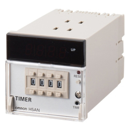

Omron H5AN-4D AC100-240 ราคา 6,925.5 บาท
฿6925.50
Omron H5AN-4D AC100-240 ราคา 6,925.5 บาท
เหลือ 0 ชิ้น
ซื้อเลย
หยิบลงตะกร้า
- หมวดหมู่ : Omron piay
- รหัสสินค้า : 070881
รายละเอียดสินค้า Omron H5AN-4D AC100-240 ราคา 6,925.5 บาท
| Rated supply voltage | 100 to 240 VAC (50/60 Hz) |
|---|---|
| Operating voltage range | 85 to 110% of rated supply voltage |
| External power supply | 12 VDC ±10% 80 mA (5% ripple max.) |
| Power consumption | Approx. 10 VA (at 240 VAC) |
| Time ranges(Number of ranges) | 8 |
| Time ranges | 0.01 to 99.99 s 0.1 to 999.9 s 1 to 9999 s 0.1 to 999.9 min 0.1 to 999.9 h 1 to 9999 h 1 s to 99 min 59 s 1 min to 99 h 59 min |
| Input method | Contact: Contact open and short-circuit input No-contact: Open-collector transistor ON/OFF input |
| Output modes | N/F/C/R/K/P/Q |
| Control output (Contact output) | SPDT Resistive load: 3 A at 250 VAC (cosφ=1) Minimum applicable load: 10 mA at 5 VDC (failure level: P Reference value) |
| Control output (Solid state output) | 1 pointTransistor output (open collector) Switching capacities: 30 VDC max., 100 mA max. |
| Reset system | Power reset/External reset/Manual reset/Automatic reset |
| Power reset | Minimum power-opening time: 0.5 s |
| External reset and Gate | Minimum input signal width: 0.02 s |
| Timer mode | Elapsed time (UP) and remaining time (DOWN) (selectable) |
| Display method | 7-segment LED 4 digit |
| Character height | 10 mm |
| Ambient temperature (Operating) | -10 to 55 ℃ (with no icing) |
| Ambient temperature (Storage) | -25 to 65 ℃ (with no icing) |
| Ambient humidity (Operating) | 35 to 85% |
| Accuracy of operating time | Power-ON start: ±0.01% ±0.05 s max. (The values are based on the set value.) Reset start: ±0.005% ±0.03 s max. (The values are based on the set value.) |
| Setting error | Power-ON start: ±0.01% ±0.05 s max. (The values are based on the set value.) Reset start: ±0.005% ±0.03 s max. (The values are based on the set value.) |
| Influence of voltage | Power-ON start: ±0.01% ±0.05 s max. (The values are based on the set value.) Reset start: ±0.005% ±0.03 s max. (The values are based on the set value.) |
| Influence of temperature | Power-ON start: ±0.01% ±0.05 s max. (The values are based on the set value.) Reset start: ±0.005% ±0.03 s max. (The values are based on the set value.) |
| Insulation resistance | Between current carrying terminals and exposed non-current carrying metal parts: 100 MΩ min. (at 500 VDC) Between non-continuous contacts: 100 MΩ min. (at 500 VDC) |
| Dielectric strength | Between current carrying terminals and exposed non-current carrying metal parts: 2000 VAC 50/60 Hz 1 min Between non-continuous contacts: 750 VAC 50/60 Hz 1 min |
| Impulse withstand voltage | Between operating power supply terminals: 6 kV Between current carrying terminals and exposed non-current carrying metal parts: 6 kV |
| Noise immunity | Between operating power supply terminals: ±2 kV Between input terminals: ±500 kV Square-wave noise by noise simulator |
| Static immunity | Mulfunction: 8 kV |
| Vibration resistance | Destruction: 10 to 55 Hz, 0.375 mm single amplitude each in 3 directions for 2 h Malfunction: 10 to 55 Hz, 0.25 mm single amplitude each in 3 directions for 10 min |
| Shock resistance | Destruction: 300 m/s2, 3 times each in 6 directions Malfunction: 100 m/s2, 4 times each in 6 directions |
| Life expectancy | Electrical: 100,000 operations min. (3 A at 250 VAC resistive load) Mechanical: 10 million operations min. |
| Mounting method | Flush mounting |
| External connection method | Screw terminal |
| Case color | Light gray (Munsell 5Y7/1) |
| Attachment | Mounting Bracket |
| Accessory (sold separately) | Mounting Bracket: Y92H-5 |
| Weight | Approx. 360 g |
รีวิว (2)

Customer
10/12/2560 13:51
คุณภาพสินค้าดีมาก
Customer
10/12/2560 13:51
คุณภาพสินค้าดีมาก
เพิ่มรีวิว
สินค้าที่เกี่ยวข้อง Omron H5AN-4D AC100-240 ราคา 6,925.5 บาท
สถิติของเว็บไซต์
เปิดเว็บเมื่อ : 17/04/2554
ปรับปรุงเว็บเมื่อ : 14/10/2569
ผู้ชมทั้งหมด :
สินค้าทั้งหมด : 517084


