LEWPLC
- หน้าแรก
- สินค้า
- Fluke piay
- Fluke 1625-2 GEO Earth Ground Tester ราคา 132,817 บาท
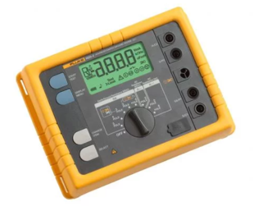

Fluke 1625-2 GEO Earth Ground Tester ราคา 132,817 บาท
฿132817.00
Fluke 1625-2 GEO Earth Ground Tester ราคา 132,817 บาท
เหลือ 0 ชิ้น
ซื้อเลย
หยิบลงตะกร้า
- หมวดหมู่ : Fluke piay
- รหัสสินค้า : 070331
รายละเอียดสินค้า Fluke 1625-2 GEO Earth Ground Tester ราคา 132,817 บาท
Specifications
Specifications: Fluke 1625-2 GEO Earth Ground Tester
| General Specifications | ||||
| Memory | Internal memory storage up to 1500 records accessible via USB port | |||
| Measuring function | Interference voltage and frequency, earthing resistance 3- and 4-pole with/without clip-on current transformer, resistance 2-pole with AC, 2- and 4-pole with DC | |||
| Display | 4 digit (2999 Digit) – 7 segment liquid crystal display, with improved visibility | |||
| Operation | Central rotary switch and function keys | |||
| Temperature Range | ||||
| Operating temperature | -10°C to 50°C (14°F to 122°F) | |||
| Storage temperature | -30°C to 60°C (-22°F to 140°F) | |||
| Temperature coefficient | ±0.1% of reading/°C < 18°C > 28°C | |||
| Type of protection | IP56 for case, IP40 for battery door according to EN60529 | |||
| Max voltage | Warning – socket “clamp” to socket E, ES, S or H | |||
| Urms = 0 V | ||||
| Sockets E, ES, S or H to each other in any combination, max. Urms = 250 V (pertains to misuse) | ||||
| Safety | Protection by double and/or reinforced insulation. Max. 50 V to earth per IEC61010-1. Pollution degree 2 | |||
| Quality standard | Developed, designed and manufactured to comply with DIN ISO 9001 | |||
| External field influence | Complies with DIN 43780 (8/76) | |||
| Auxiliary power | 6 x 1.5 V alkaline (IEC LR6 or type AA) | |||
| Battery life span | With IEC LR6/type AA: typ. 3,000 measurements (RE+RH ≤ 1 kΩ) | |||
| With IEC LR6/type AA: typ. 6,000 measurements (RE + RH > 10 kΩ) | ||||
| Dimensions (W x H x D) | 250 x 133 x 187 mm (9.75 x 5.25 x 7.35 in) | |||
| Weight | ≤ 1.1 kg (2.43 lb) without accessories 7.6 kg (16.8 lb) incl. accessories and batteries in carrying case | |||
| Case material | Polyester | |||
| Measurement of Interference Voltage DC + AC (UST) | ||||
| Measuring limits of error: method | Full wave rectification | |||
| Measuring range | 1 V to 50 V | |||
| Display range | 0.0 V to 50 V | |||
| Resolution | 0.1 V | |||
| Frequency range | DC/AC 45 Hz to 400 Hz sine | |||
| Accuracy | ±(5% of rdg + 5 digit) | |||
| Measuring sequence | Approx. 4 measurements/s | |||
| Internal resistance | Approx. 1.5 MΩ | |||
| Max. overload | Urms = 250 V | |||
| Measurement of Interference Frequency (F) | ||||
| Measuring limits of error: method | Measurement of oscillation period of the interference voltage | |||
| Measuring range | 6.0 Hz to 400 Hz | |||
| Display range | 16.0 Hz to 299.9 Hz to 999 Hz | |||
| Resolution | 0.1 Hz to 1 Hz | |||
| Range | 1 V to 50 V | |||
| Accuracy | ±(1% of rdg + 2 digit) | |||
| Earthing Resistance (RE) | ||||
| Measuring method | Current and voltage measurement with probe as IEC61557-5 | |||
| Open circuit voltage | 20/48 V, AC | |||
| Short circuit current | 250 mA AC | |||
| Measuring frequency | 94, 105, 111, 128 Hz selected manually or automatic. (AFC) 55 Hz in function R1 | |||
| Noise rejection | 120 dB (16 2/3 , 50 , 60, 400 Hz) | |||
| Max. overload | Urms = 250 V | |||
| Electrical Measurement Specifications | ||||
| Intrinsic Error or Influence Quantity | Reference Conditions or Specified Operating Range | Designation Code | Requirements or Test in Accordance with the Relevant Parts of IEC 1557 | Type of Test |
| Intrinsic error | Reference conditions | A | Part 5, 6.1 | R |
| Position | Reference position ±90° | E1 | Part 1, 4.2 | R |
| Supply voltage | At the limits stated by the manufacturer | E2 | Part 1, 4.2, 4.3 | R |
| Temperature | 0°C and 35°C | E3 | Part 1, 4.2 | T |
| Series interference voltage | See 4.2 and 4.3 | E4 | Part 5, 4.2, 4.3 | T |
| Resistance of the probes and auxiliary earth electrodes | 0 to 100 x RA but ≤ 50 kΩ | E5 | Part 5, 4.3 | T |
| System frequency | 99% to 101% of the nominal frequency | E7 | Part 5, 4.3 | T |
| System voltage | 85% to 110% of the nominal voltage | E8 | Part 5, 4.3 | T |
| Operating error | B = ±(|A| + 1,15 √E21 E22 E23 E24 E25 E26 ) | Part 5, 4.3 | R | |
| B[%] = ± B/fiducial value x 100% A = intrinsic error | ||||
| Measuring range | 0.020 Ω to 300 kΩ | |||
| Display range | 0.001 Ω to 2.999 Ω | |||
| 3.00 Ω to 29.99 Ω | ||||
| 30.0 Ω to 299.9 Ω | ||||
| 0.300 kΩ to 2.999 kΩ | ||||
| 3.00 kΩ to 29.99 kΩ | ||||
| 30.0 kΩ to 299.9 kΩ | ||||
| Resolution | 0.001 Ω | |||
| 0.01 Ω | ||||
| 0.1 Ω | ||||
| 1 Ω | ||||
| 10 Ω | ||||
| 100 Ω | ||||
| Accuracy | ±(2% of rdg + 2 digit) | |||
| Operating error | ±(5% of rdg + 5 digit) | |||
| Measuring time | Typical 8 seconds with a fixed frequency 30 sec. max. with AFC and complete cycle of all measuring frequencies | |||
| Additional error because of probe-and auxiliary earth electrode resistance | RH(RS + 2000 Ω)/RE x 1.25 x 10⁻⁶% + 5 digits | |||
| Measuring error of RH and RS | Typ. 10% of RE + RS + RH | |||
| Max. probe resistance | ≤ 1 MΩ | |||
| Max. auxiliary earth electrode resistance | ≤ 1 MΩ | |||
| Automatic check if error is kept within the limits required by IEC61557-5. If after a measurement of probe-, auxiliary earth electrode- and earthing resistance, a measurement error of higher than 30% is assumed because of the influencing conditions, the display shows a warning symbol and a notice that RS or RH are too high. | ||||
| Automatic Switchover of Measuring Resolution in Dependence to Auxiliary Earth Electrode Resistance RH | ||||
| RH with Umeas = 48 V | < 300 Ω | |||
| < 6 Ω | ||||
| < 60 Ω | ||||
| < 600 Ω | ||||
| RH with Umeas = 20 V | < 250 Ω | |||
| < 2.5 kΩ | ||||
| < 25 kΩ | ||||
| < 250 kΩ | ||||
| Resolution | 1 mΩ | |||
| 10 mΩ | ||||
| 100 mΩ | ||||
| 1 Ω | ||||
| Selective Measurement of the Earthing Resistance (RE Clamp) | ||||
| Measuring method | Current and voltage measurement with probe as per EN61557-5 and current measurement in the individual branch with additional current transformer (patent applied for). | |||
| Open circuit voltage | 20/48 V AC | |||
| Short circuit current | 250 mA AC | |||
| Measuring frequency | 94, 105, 111, 128 Hz selected manually or automatically (AFC), 55 Hz (R1) | |||
| Noise rejection | 120 dB (162/3, 50, 60, 400 Hz) | |||
| Max. overload | Max. Urms = 250 V (measurement will not be started) | |||
| Measuring range | 0.020 Ω to 300 kΩ | |||
| Display range | 0.001 Ω to 2.999 Ω | |||
| 3.00 Ω to 29.99 Ω | ||||
| 30.0 Ω to 299.9 Ω | ||||
| 0.300 kΩ to 2.999 kΩ | ||||
| 3.00 kΩ to 29.99 kΩ | ||||
| Resolution | 0.001 Ω | |||
| 0.01 Ω | ||||
| 0.1 Ω | ||||
| 1 Ω | ||||
| 10 Ω | ||||
| Accuracy | ±(7% of rdg + 2 digit) | |||
| Operating error | ±(10% of rdg + 5 digit) | |||
| Additional error because of probe- and auxiliary earth typ. electrode resistance | RH(RS + 2000 Ω)/RETOTAL x 1.25 x 10⁻⁶% + 5 digits | |||
| Measuring error of RH and RS | Typ. of 10% of RETOTAL + RS + RH | |||
| Measuring time | Typ. 8 sec. with a fixed frequency 30 sec. max. with AFC and complete cycle of all measuring frequencies. | |||
| Minimal current in single branch to be measured | 0.5 mA | With transformer (1000:1) | ||
| 0.1 mA | With transformer (200:1) | |||
| Max. interference current through transformer | 3 A | With transformer (1000:1) | ||
| 1. With recommended current clamps/transformers. | ||||
| Resistance Measurement (R~) | ||||
| Measuring method | Current and voltage measurement | |||
| Measuring voltage | 20 V AC, square pulse | |||
| Short circuit current | > 250 mA AC | |||
| Measuring frequency | 94, 105, 111, 128 Hz selected manually or automatically (AFC) | |||
| Measuring range | 0.020 Ω to 300 kΩ | |||
| Display range | 0.001 Ω to 2.999 Ω | |||
| 3.00 Ω to 29.99 Ω | ||||
| 30.0 Ω to 299.9 Ω | ||||
| 300 Ω to 2999 Ω | ||||
| 3.00 kΩ to 29.99 kΩ | ||||
| 30.0 kΩ to 299.9 kΩ | ||||
| Resolution | 0.001 Ω | |||
| 0.01 Ω | ||||
| 0.1 Ω | ||||
| 1 Ω | ||||
| 10 Ω | ||||
| 100 Ω | ||||
| Accuracy | ±(2% of rdg + 2 digit) | |||
| Operating error | ±(5% of rdg + 5 digit) | |||
| Measuring time | Typical 6 seconds | |||
| Max. interference voltage | 24 V, with higher voltages measurement will not be started | |||
| Max overload | Urms max. = 250 V | |||
| Resistance Measurement (R DC) | ||||
| Measuring method | Current- voltage measurement as per IEC61557-4 possible | |||
| Measuring voltage | 20 V DC | |||
| Short circuit current | 250 mA DC | |||
| Formation of measured value | With 4-pole measurement wires on H, S, ES can be extended without additional error. Resistances > 1 Ω in wire E can cause additional error of 5m Ω/Ω. | |||
| Measuring range | 0.020 Ω to 300 kΩ | |||
| Display range | 0.001 Ω to 2.999 Ω | |||
| 3.00 Ω to 29.99 Ω | ||||
| 30.0 Ω to 299.9 Ω | ||||
| 300 Ω to 2999 Ω | ||||
| 3.0 kΩ to 29.99 kΩ | ||||
| 30.0 kΩ to 299.9 kΩ | ||||
| Resolution | 0.001 Ω | |||
| 0.01 Ω | ||||
| 0.1 Ω | ||||
| 1 Ω | ||||
| 10 Ω | ||||
| 100 Ω | ||||
| Accuracy | ±(2% of rdg + 2 digit) | |||
| Operating error | ±(5% of rdg + 5 digit) | |||
| Measuring sequence | Approx. 2 measurements/s | |||
| Measuring time | Typical 4 second including reversal of polarity (2-pole or 4-pole) | |||
| Maximum interference voltage | ≤ 3 V AC or DC, with higher voltages measurement will not be started | |||
| Maximum inductivity | 2 Henry | |||
| Maximum overload | Urms = 250 V | |||
| Compensation of Lead Resistance (RK) | ||||
| Compensation of lead resistance (RK) can be switched on in functions RE 3-pole, RE 4-pole (clamp), R AC, and R DC 2-pole | ||||
| Formation of measured value | Rdisplay = Rmeasured – Rcompensated2 | |||
| 2. Value of setpoint entry RK = 0.000 Ω, variable from 0.000 to 29.99 Ω by means of measuring adjustment. | ||||
| Stakeless Ground Loop Measurement (Two Clamp Stakeless) | ||||
| Switch position | RA 4-pole (two clamp Stakeless) | |||
| Resolution | 0.001 Ω to 0.1 Ω | |||
| Measuring range | 0.02 Ω to 199.9 Ω | |||
| Accuracy | ±(7% rdg + 3 digit) | |||
| Operating error | ±(10% rdg + 5 digit) | |||
| Measuring voltage | Vm = 48 V AC (primary) | |||
| Measuring frequency | 128 Hz | |||
| Noise current (IEXT) | Max. IEXT = 10 A (AC) (RA < 20 Ω) | |||
| Max. IEXT = 2 A (AC) (RA > 20 Ω) | ||||
รีวิว (2)

Customer
10/12/2560 13:51
คุณภาพสินค้าดีมาก
Customer
10/12/2560 13:51
คุณภาพสินค้าดีมาก
เพิ่มรีวิว
สินค้าที่เกี่ยวข้อง Fluke 1625-2 GEO Earth Ground Tester ราคา 132,817 บาท

สถิติของเว็บไซต์
เปิดเว็บเมื่อ : 17/04/2554
ปรับปรุงเว็บเมื่อ : 14/10/2569
ผู้ชมทั้งหมด :
สินค้าทั้งหมด : 517084


